Introduction
This post builds upon the previous one, and expounds some of the details of the communication interface between the PIC32 Parallel Master Port module and LCD panel controllers – ILI9486L and HX8347G.
Implementation
Both the display controllers support the 16 bit Intel 8080 Mode with 16BPP. The Intel 8080 mode defines 4 control lines in addition to the 16 bit Data Bus and that is what I am using. The control lines are – RDS (Read Strobe, WRS (Write Strobe), Data/Command (D/C#) Select (also called Register Select). As is evident from the names, the Read and Write strobes are used to latch the data on the bus. So to Write data on the bus, the PMP loads data (D0 – D16) and then pulls the WRS line low, when the WRS is pulled High, the display controller latches the data on the bus. Similarly for a Read, the Host PMP pulls the RDS line Low, the controller outputs data on the bus and the host reads this data on the RDS Low to High transition. The D/C# line is used to indicate to the controller whether the master is sending a command or writing/reading data.
If you are using the PIC32′s PMP, the RDS and WRS strobes are generated automatically by the hardware when you Read and Write the PMP data register. Only the D/C# and CS lines need to be generated in the driver. Typical Write and Read operations with the PMP looks like this:
1 2 3 4 5 6 7 8 9 10 11 12 13 14 15 16 17 18 19 20 21 22 23 24 | |
The next task is to write a pixel in the display controller GRAM. HX8342 defines the following table for writing pixel data in the 16 bit mode:
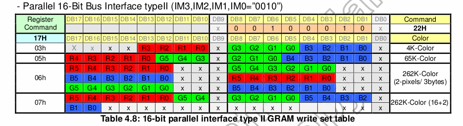
What this indicates is that the color depth is controlled by setting the register 0x17 to 3, 5 6 or 7. We use 65K so we set it at 0x05. The command 0x22 is the RAMWR command which should be followed with the 16BPP data. The pixel address is set by manipulating the Start Column and Start Page registers as mentioned in the introductory post. So PutPixel on HX8347 looks like this:
1 2 3 4 5 6 7 8 9 10 11 12 13 14 15 16 17 | |
This can be extended to implement GetPixel and so on. In the case of IL9486 the SC/SP values are stored in one register, so you just need to send one command followed by the “parameters”. PutPixel looks like this:
1 2 3 4 5 6 7 8 9 10 11 12 13 14 15 16 17 | |
Finally, the display orientation depends on the setting of some bits usually denoted by MX, MY and MV. You should be able to see their significance from your controller datasheet..